Geometric dimensioning and tolerancing (GD&T) communicates engineering tolerances and design intent through engineering drawings. GD&T ensures that manufactured parts meet quality standards within specified tolerances. This typically involves measuring, inspecting, testing, or verifying various features on a part and comparing them to standards and specifications (such as CAD models) to determine if they meet requirements.
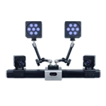
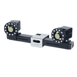
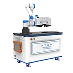
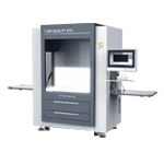
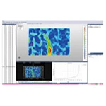
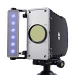
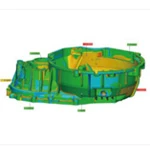
The XTOP3D XTOM blue-light 3D scanner analyzes parts by capturing shape, geometry, and texture data, which is then used to construct a digital 3D model. When combined with inspection software, it can perform geometric tolerance analysis and generate detailed inspection reports, effectively meeting measurement quality or geometric dimensioning and tolerancing (GD&T) requirements for first article inspection (FAI), quality control (QC), and quality assurance (QA) during the manufacturing process.
1. Basic Definition
Dimensional tolerance refers to the actual deviation from theoretical dimensions due to manufacturing errors during the remanufacturing process. To ensure interchangeability of parts, improve production efficiency, and reduce costs, dimensional errors must be controlled within a certain range. This permissible range of dimensional variation is called the dimensional tolerance, which includes length and width.
Form and position tolerances: Form refers to shape, while position refers to position. These two are collectively referred to as form and position tolerances. Due to the inherent performance of parts or the need for assembly, they inevitably have relative positions or properties. Therefore, the form and position tolerances of parts must also be controlled within a certain range.
2. Tolerance principle
2.1. Principle of Independence
The principle of independence means that dimensional tolerances and form and position tolerances are independent of each other. Each size, shape and position requirement given on the drawing is independent and should be met separately.
2.2 Relevant Principles
The principle of correlation states that dimensional tolerances and form and position tolerances are interrelated. This principle includes containment requirements, maximum material requirements, and minimum material requirements.
Understanding this principle requires understanding the following dimensions:
1) External Effective Dimension: The effective dimension of a single feature, referred to as the effective dimension (MS), is the combined result of actual size and form errors. For a given length of the measured feature, the diameter or width of the largest ideal surface that externally contacts the actual internal surface (hole) or the smallest ideal surface that externally contacts the actual external surface (shaft) is called the external effective dimension, commonly referred to as the effective dimension. This dimension is the effective dimension that affects the assembly process and is the result of the combined effect of actual dimensions and form and position errors. It exists on the part itself, not on the drawing.
For example, the external effective dimension (dfe) of a shaft is the dimension of the smallest ideal hole that fits the shaft; the external effective dimension (Dfe) of a hole is the dimension of the largest ideal shaft that fits the hole.
聯(lián)示意圖")
2) In-body effective dimension: The diameter or width of the smallest ideal surface that is in contact with the actual inner surface (hole) in-body, or the largest ideal surface that is in contact with the actual outer surface (shaft) in-body, at a given length of the measured element, is called the in-body effective dimension.
作用尺寸")
The following are three requirements within these principles:
1) Inclusion Requirements within These Principles:
On a drawing, if a symbol is added after the dimensional limit deviation or tolerance zone designation for a single element, it indicates that the element adopts inclusion requirements. This inclusion requirement means that the actual element must adhere to its maximum physical boundaries. This means that the element's in-vitro effective dimensions must not exceed its maximum physical boundaries, and its local actual dimensions must not exceed its minimum physical dimensions.
原則中的包容要求")
In the above drawing, if the actual cylindrical surface passes a full-form gauge with a diameter equal to the maximum material boundary dimension of 20 mm and the total actual local dimension measured at two points is greater than or equal to 19.97 mm, the part is considered acceptable. The inclusion requirement is a tolerance requirement that simultaneously controls both the actual dimension and the geometric error within the dimensional tolerance range.
2) Maximum Material Requirement
On the drawing, a symbol following the tolerance value or datum letter in the geometric tolerance box indicates that the maximum material requirement applies to the measured feature and the datum feature, respectively.
Applying the Maximum Material Requirement to the Measured Feature:
When the Maximum Material Requirement is applied to the measured feature, the geometric tolerance value for the measured feature is given when the feature is in its maximum material state. When the measured feature's actual contour deviates from its maximum material state, that is, when the local actual dimension deviates from the maximum material dimension, the geometric error value may exceed the geometric tolerance value given in the maximum material state, with the maximum excess equal to the dimensional tolerance of the measured feature. At the same time, the local actual dimension must not exceed its maximum and minimum material dimensions.
體要求應(yīng)用于被測要素")
The straightness tolerance of the axis shown in Figure a adopts the maximum material requirement. When the axis is in its maximum material state, its straightness tolerance is 0.01mm (Figure b). As the actual dimensions of the axis deviate from the maximum material state, the allowable straightness error f of the axis may increase accordingly. The corresponding relationship is shown in the tolerance zone diagram in Figure c.
During inspection, the actual cylindrical profile of the axis passes through a position gauge made to the maximum material effective boundary dimension of 20.01mm. Local actual dimensions measured using the two-point method are considered acceptable if they fall within the maximum and minimum material dimensions.
The dynamic tolerance zone diagram shows that as the actual dimension decreases from 20mm to the maximum material state, the allowable straightness error f is allowed to increase accordingly, but the maximum increase must not exceed the dimensional tolerance, thus achieving the conversion from dimensional tolerance to geometric tolerance.
3) Minimum Material Requirement
When the symbol is added after the tolerance value or datum letter in the geometric tolerance box on the drawing, it indicates that the minimum material requirement is adopted for the measured feature or datum feature, respectively.
Minimum Material Requirements Applied to Measured Requirements
When the minimum material requirement is applied to a measured element, the measured element's actual contour must not exceed its minimum material effective boundary at any point along a given length, and its local actual dimensions must not exceed its maximum and minimum material dimensions.
When the minimum material requirement is applied to a measured element, the geometric tolerance values for the measured element are given when the element is in its minimum material state. If the measured element's actual contour deviates from its small material state, that is, if its actual dimensions deviate from its minimum material dimensions, the geometric error values may exceed the geometric tolerance values given for the minimum material state. In this case, the measured element's in-body effective dimensions must not exceed its minimum material effective boundary dimensions. (As shown in the figure below)
體要求應(yīng)用于被測要求")
3. Selection of tolerance principle:
The functional requirements of the measured element should be considered to fully utilize the function of tolerances and the feasibility and cost-effectiveness of the tolerance principle.
The independence principle is used when dimensional accuracy and form and position accuracy requirements differ significantly and must be met separately, or when there is no correlation between the two, to ensure kinematic accuracy and sealing, and when no tolerances are specified.
The inclusion requirement is primarily used when strict fit requirements must be met.
The maximum material requirement is used for central elements and is generally used when the assembly requirement for the components is for fit (no fit requirements).
The minimum material requirement is primarily used when part strength and minimum wall thickness must be guaranteed.


立原則示意圖")
作用尺寸示意圖")


