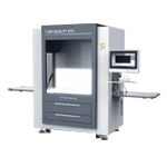
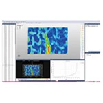
Blue light 3D scanning technology is a high-precision dimensional measurement method that can scan objects into 3D data models and, combined with inspection software, conduct a series of geometric tolerance analyses.
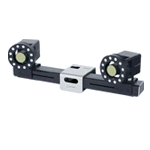
The XTOP3D XTOM blue light 3D scanner can capture minute contour details of components, and dimensional deviations are marked with different colors to help manage molding quality and assembly accuracy.
In geometric tolerance analysis, geometric tolerance annotation is crucial, yet achieving it quickly and accurately is undoubtedly challenging. Irrational and inaccurate geometric tolerance annotation not only hinders the reading of part drawings but also affects the positioning and clamping relationships of parts.
注示意圖")
Therefore, it is very important to master the knowledge of geometric tolerance marking. The marking methods of geometric tolerance are generally divided into the marking of tolerance grid, the marking of measured elements, the marking of datum elements and the marking of tolerance values.
The specific marking method is as follows:
1.Marking of tolerance grid
(1) Tolerance grids and their contents
Tolerance grids are generally placed horizontally on the drawing, but can be placed vertically if necessary. For horizontal placement, the tolerance item, tolerance value and related symbols, datum letter and related symbols should be filled in from left to right. The number of tolerance grids is usually 2 to 5, depending on the content to be filled in, as shown in Figure 1.

Figure 1 Tolerance Grid
(2) Guide Lines: The tolerance grid is connected to the measured element by a guide line. The guide line consists of a thin solid line and an arrow. It extends from one end of the tolerance grid and remains perpendicular to the end line of the tolerance grid. It is allowed to bend when leading to the measured element, but not more than twice. The arrow of the guide line should point in the width direction or radial direction of the tolerance zone, as shown in Figure 2.
準(zhǔn)示例")
Figure 2 Example of geometric tolerance standards
(3) Datum symbol and datum code
Datum symbol. It is a bold dash.
Datum code. It consists of the datum symbol, a circle, a line, and letters. Regardless of the orientation of the datum symbol, the letters should be written horizontally. See Figure 3.
符號(hào)及代號(hào)")
Figure 3 Reference symbols and codes
2. Standards for the measured element
(1) When the measured element is a contour element, the indicator arrow should point to the visible contour line of the measured surface, or to the extension line of the contour line, and must be clearly offset from the dimension line, as shown in Figure 4 (a).
(2) When a geometric tolerance requirement is made for a surface in a view, a small black dot can sometimes be used to draw a reference line on the surface, and the guide line arrow of the tolerance box should point to the reference line, as shown in Figure 4 (b).
注")
Figure 4 Contour feature annotation
(3) When the measured element is a central element such as a center point, center of a circle, axis, center line, or center plane, the arrow of the guide line should be aligned with the dimension line, that is, coincide with the extension line of the dimension line. If the arrow of the guide line and the arrow of the dimension line are in the same direction, they can be combined into one, as shown in Figure 5.

Figure 5 Center Feature Marking
3. Datum Feature Marking
(1) When the datum feature is a contour feature such as an edge or surface, the short horizontal line in the datum code should be close to the contour line or contour surface of the datum feature, or close to the extension line of the contour, but it should be clearly offset from the dimension line, as shown in Figure 6(a).
(2) When the datum code must be marked on a certain surface due to graphic restrictions, a small black dot can be drawn on the surface, and a reference line can be drawn from the black dot. The datum code is placed on the reference line, as shown in Figure 6(b). It should be a circular surface.
Figure 6 Profile datum elements
(3) When the datum feature is a central feature such as a center point, axis, or center plane, the line connecting the datum code should be aligned with the dimension of the feature, as shown in Figure 7(a). The short dash in the datum code can also replace one of the arrows on the dimension line, as shown in Figure 7(b).
(4) When the datum feature is the axis of a cone, the line connecting the datum code should be perpendicular to the datum feature, that is, it should be perpendicular to the axis rather than the cone's element line, and the datum short dash should be parallel to the cone's element line, as shown in Figure 7(c).
Figure 7 Center datum feature
(5) When the local range of an element is used as a reference, its location must be indicated by a thick dotted line and the corresponding range and position dimensions must be marked, as shown in Figure 8.
(6) When a datum target is used, appropriate points, lines, or partial surfaces should be given on the relevant surface to represent the datum feature. When the datum target is a point, it is represented by a 45° cross thick solid line, as shown in Figure 9(a); when the datum target is a straight line, it is represented by a thin solid line, and a 45° cross thick solid line is added to the edge, as shown in Figure 9(b); when the datum target is a partial surface, the partial surface outline is drawn with a double-dashed line, and a thin solid line inclined at 45° is drawn in the middle, as shown in Figure 9(c).
")
Figure 8 Local benchmark
Figure 9 Datum Target
4. Tolerance value marking
The tolerance value represents the width or diameter of the tolerance zone and serves as an indicator of the amount of error to be controlled. The size of the tolerance value directly reflects the accuracy of the geometric and positional tolerances.
The tolerance value is indicated in the second cell of the tolerance grid. For the width of the tolerance zone, only the tolerance value t is indicated. For the diameter of the tolerance zone, φt or Sφt should be indicated, depending on the feature characteristics and design requirements.
If there are further requirements for the tolerance value beyond the numerical value, such as allowing the error value to only be convex in the middle and not concave, or to only decrease or increase from one end to the other, a restriction symbol (see Table 1) should be used and indicated after the tolerance value.
Table 1 Restricted Symbols
注:公差值限制符號(hào)表")


要素的標(biāo)注")
要素")
目標(biāo)示意圖")


