Next, we will share the third article in the geometric tolerance series, which mainly introduces the practical knowledge of form and position tolerances. It introduces parallelism, verticality, inclination, position, coaxiality, symmetry, circular runout, and total runout in form and position tolerances respectively, and draws diagrams to illustrate each marking method.

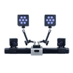
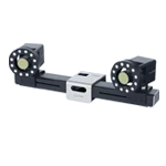
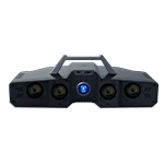
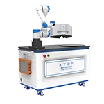
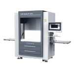
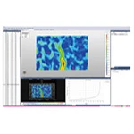
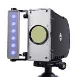
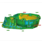
As product structure design becomes more complex and diverse, more and more parts or products require three-dimensional size and form and position tolerance detection. To meet this need, it is often necessary to use a high-precision blue light 3D scanner to quickly obtain 3D drawings, compare the scanned data with the CAD data, analyze the geometric tolerance and deviation annotations, and make the constructed samples more in line with product requirements.

高精度藍光三維掃描儀用于注塑件幾何公差分析
1. Concept and its impact
Positional tolerance is the deviation between the expected position of a feature and its actual position relative to a datum. It is a tolerance specification that describes the positional relationship between parts. Before specifying positional tolerance, the datum must be determined. Therefore, positional tolerance is a factor associated with the datum, that is, a geometric tolerance of the associated factor.
Positional tolerance focuses on the relative positional relationship between parts, such as the distance between the centers of two holes or the parallelism between two planes. Form tolerance focuses on the geometric characteristics of a part, such as the diameter of a circle or the straightness of a cylinder. When designing and manufacturing parts, form and positional tolerances must be considered together to ensure part functionality, assembly performance, and manufacturing feasibility. Properly defining and controlling positional and form tolerances can achieve high-quality part manufacturing and assembly.
2. Classification
According to the functional requirements of the associated elements for the datum, position tolerances can be specifically divided into three categories: orientation tolerance, positioning tolerance and runout tolerance. The classification of position tolerances is presented in the form of a table below.
Table 1 Classification of geometric tolerances

Orientation tolerances: parallelism, perpendicularity, and tilt
Positioning tolerances: position, coaxiality, and symmetry
Runout tolerances: circular runout and total runout
3. Definition and representation of tolerances at different positions
An orientation tolerance is the total amount of allowable directional variation of an associated feature relative to a datum. The orientation of an orientation tolerance zone is fixed, determined by the datum, while its position can vary within the dimensional tolerance zone. An orientation tolerance zone controls both directional and form errors of the measured feature. This type of tolerance includes parallelism, perpendicularity, and inclination.
Table 1 Definition and examples of orientation tolerance

Parallelism, commonly referred to as the degree of parallelism, indicates whether the actual feature being measured on a part remains equidistant from the datum. The parallelism tolerance is the maximum allowable deviation between the actual orientation of the feature being measured and its ideal orientation, which is parallel to the datum. The plane indicated by the arrow must lie between two planes parallel to datum plane A and separated by only 0.05 mm from the direction of the arrow.
Perpendicularity, commonly referred to as the degree of orthogonality between two features, indicates whether the measured feature on a part maintains a correct 90° angle with respect to the datum. The perpendicularity tolerance is the maximum allowable deviation between the actual orientation of the feature being measured and its ideal orientation, which is perpendicular to the datum. The plane indicated by the arrow must lie in parallel planes perpendicular to datum plane A, with a separation of 0.03 mm between the two parallel planes.
Tilt indicates whether two features on a part maintain their relative orientation at any given angle. The tilt tolerance is the maximum allowable deviation between the actual orientation of the feature being measured and its ideal orientation, which is perpendicular to the datum, at any given angle. The surface indicated by the arrow must exhibit a theoretical inclination of exactly 45° with respect to datum plane A and lie between two parallel planes separated by a distance of only 0.3 mm in the direction of the arrow.
Positional tolerance refers to the total allowable variation in the position of an associated feature relative to the datum. The positional tolerance zone is fixed relative to the datum. It controls both positional errors of the measured feature and errors in its orientation and form.
Table 2 Definition and examples of positioning tolerance

Position accuracy indicates the accuracy of points, lines, surfaces, and other features on a part relative to their ideal position. Position tolerance is the maximum allowable variation of the measured feature's actual position relative to its ideal position.
The center point of the circle indicated by the marking arrow must lie within circle a with a diameter of 0.1 mm.
Coaxiality, commonly referred to as the degree of coaxiality, indicates whether the measured axis on a part remains aligned with the datum axis. The coaxiality tolerance is the allowable variation of the measured axis relative to the datum axis.
The axis of a cylinder indicated by the marking arrow must lie within a 0.03 mm diameter cylinder centered on datum axis line A.
Symmetry indicates whether two symmetrical central features on a part remain in the same central plane. The symmetry tolerance is the allowable variation of the actual feature's center plane (or center line, or axis) relative to the ideal symmetry plane.
The center plane indicated by the marking arrow must lie between two parallel planes symmetrically spaced 0.05 mm from datum center plane A.
Runout tolerance: Runout tolerance is the maximum allowable runout of an associated element when rotating one or more rotations around the datum axis. Runout tolerance is categorized as circular runout and total runout. Runout is a comprehensive reflection of certain form and position errors.
Table 3 Runout tolerance definition and examples

Circular runout refers to the condition of a rotating surface on a part that maintains a fixed position relative to the datum axis within a defined measuring plane. The circular runout tolerance is the maximum allowable variation within the defined measuring range when the measured element rotates one full revolution about the datum axis without axial movement.
During one linear rotation about the datum axis, the radial runout of the cylindrical surface indicated by the marking arrow on any measuring plane perpendicular to the datum axis must not exceed 0.03 mm.
Total runout refers to the runout along the entire measured surface when the part is continuously rotated about the datum axis. The total runout tolerance is the maximum allowable runout when the measured element is continuously rotated about the datum axis while the indicator moves relative to its ideal profile.
When a cylindrical part is linearly rotated about the datum axis, the radial runout of the cylindrical surface indicated by the marking arrow at any point on the cylindrical surface must not exceed 0.03 mm.