Regarding the introduction of the series of special articles on geometric tolerances, the previous topic shared was: Geometric Tolerance Special Lecture 1: Dimensional Tolerance and Fit - Key Factors in Manufacturing. This time, the editor will share with you the concept, classification and definition of form and position tolerances, and clearly show examples of form and position tolerances in the form of charts.
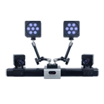
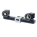
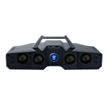
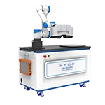
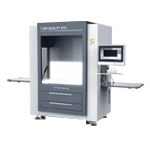
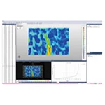
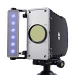
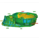
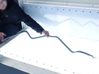
Blue-light 3D scanning technology provides a solution for 3D form and position tolerance testing. 3D models captured by blue-light 3D scanning can be imported into inspection software. By defining the required form and position tolerance specifications and requirements, discrepancies between actual measurements and design requirements can be intuitively analyzed. Understanding form and position tolerances facilitates product geometric tolerance control and assesses part compliance with specifications.
XTOP3D XTOM blue light 3D scanner for geometric and positional tolerance analysis
1. Concept and its impact
Form and position tolerances, also commonly referred to as geometric tolerances, include both shape and position tolerances and are the allowable range of geometric error. Machined parts will have dimensional tolerances. Consequently, the actual shape or relative position of the points, lines, and surfaces that comprise the part's geometric features differ from the shape and relative position specified by the ideal geometry. This difference in shape is the form tolerance, while the difference in relative position is the position tolerance. These differences are collectively referred to as form and position tolerances.
During the manufacturing process of mechanical parts, due to machining and assembly, shape and position errors are inevitable. These errors determine the geometric accuracy of the workpiece, impacting product performance, noise, lifespan, and fit, ultimately determining product quality.
2. Classification of geometric tolerances
Based on the geometric tolerance feature, tolerance zones can be divided into form tolerance, profile tolerance, and position tolerance. To more clearly explain the classification relationship between tolerance zones for each item, the following table presents the classification of behavioral tolerances.
Table 1 Classification of geometric tolerances

Form tolerances: straightness, flatness, roundness, and cylindricity
Profile tolerances: line profile and surface profile
Position tolerances: parallelism, perpendicularity, inclination, position, coaxiality and symmetry, circular runout, and total runout
3. Definition of shape tolerance
Form tolerance refers to the errors in the geometric shape of points, lines, surfaces, and other geometric features on a part that may occur during machining. Table 1 provides definitions and examples of various form tolerance items.
Table 1 Definition and examples of shape tolerance

Straightness, commonly known as flatness, indicates how well the actual shape of a linear feature on a part remains an ideal straight line. The straightness tolerance is the maximum allowable deviation of the actual line from the ideal straight line.
Within a given plane, the tolerance zone must lie between two parallel lines separated by 0.1mm.
Flatness, commonly known as flatness, indicates how well the actual shape of a planar feature on a part remains an ideal flat surface. The flatness tolerance is the maximum allowable deviation of the actual surface from the ideal flat surface.
The tolerance zone is the area between two parallel planes separated by 0.08mm.
Roundness, commonly known as roundness, indicates how well the actual shape of a circular feature on a part remains equidistant from its center. The roundness tolerance is the maximum allowable deviation of the actual circle from the ideal circle on the same cross-section.
The tolerance zone must lie between two concentric circles with a radius difference of 0.03mm on the same normal cross-section.
Cylindricity indicates how well all points on the cylindrical surface of a part remain equidistant from its axis. Cylindricity tolerance is the maximum allowable variation of an actual cylindrical surface from an ideal cylindrical surface.
The tolerance zone is the area between two coaxial cylindrical surfaces with a radius difference of 0.1 mm.
Profile tolerance is a geometric tolerance that ensures that surface elements fall within specified constant boundaries along the true profile. The definition and examples of profile tolerances are shown in Table 2.
Table 2 Definition and examples of profile tolerance
Line profile describes how well a curve of any shape on a given plane of a part maintains its ideal shape. Line profile tolerance refers to the allowable variation of the actual profile of a non-circular curve.
A tolerance zone is defined by the area between two lines enclosing a series of circles with a diameter tolerance of 0.04 mm. The centers of these circles lie on a line with theoretically correct geometry.
Surface profile describes how well a surface of any shape on a part maintains its ideal shape. Surface profile tolerance refers to the allowable variation of the actual profile of a non-circular surface from the ideal profile.
A tolerance zone is defined by two lines enclosing a series of spheres with a diameter of 0.02 mm. The centers of these spheres are theoretically located on a surface with theoretically correct geometry.